Here is my English Translation.aalea wrote:SD image is on a mega link, you should not need any permission to download it, if you continue to have problems, tell me and I upload to other place.Derek_Stewart wrote:I read all the Oqtadrive thread on va-de-retro.com and tried to register as a user, but could not to seek permission to use the SD Card image.alvaroalea wrote: Hi, I think I'm the creator of the SD image you refer, yes, in fact this image has only be tested with the PCB that have 2 led.
In any case I don't think that using other PCB shall be a problem.
I have converted the instructions to English, as my Spanish is only good for ordering Wine and Beer...
https://mega.nz/folder/pEw1GKrY#hOOKJEAZ5YhjhZrtvCxErg
If you send me the instruction in english I will upload to the same place so everybody can use.
OqtaDrive
-
Derek_Stewart

- Font of All Knowledge
- Posts: 4866
- Joined: Mon Dec 20, 2010 11:40 am
- Location: Sunny Runcorn, Cheshire, UK
Re: RE: Re: OqtaDrive
Regards, Derek

Re: RE: Re: OqtaDrive
Thank You, I update the folder.Derek_Stewart wrote: Here is my English Translation.
Re: RE: Re: OqtaDrive
I've uploaded the case with only one LED hole, https://www.thingiverse.com/thing:4917845Derek_Stewart wrote:Hi Popopo,Popopo wrote:Hi Derek,Derek_Stewart wrote: I have converted the instructions to English, as my Spanish is only good for ordering Wine and Beer...
Alvaro already answered you, about the translation, Google Translator does it fine enough, but if you have any trouble I will help you with any translation.
About the case, I have both, the original one that I bought in a Retroradionics (a replica) and the printed cases for 2 leds, keep in mind...LEDs get too down, so not to solder them close to the board, size them firstly before solderin...
I cannot show a photo now, pay attempt-ion on the pictures from the VaDeRetro forum.
Thank you for the information on the fitting of the LEDs, I will bear this in mind in construction of the v1.1 Case and PCB.
Since there is no case for the v1.2b PCB yet, I might alter the v1.1 case to only have 1 LED.
-
Derek_Stewart
- Font of All Knowledge
- Posts: 4866
- Joined: Mon Dec 20, 2010 11:40 am
- Location: Sunny Runcorn, Cheshire, UK
Re: OqtaDrive
Thanks Tom
I have arrangrd for a sample print of the STL files, see if they can do them as good as your one.
I have arrangrd for a sample print of the STL files, see if they can do them as good as your one.
Regards, Derek

Re: RE: Re: OqtaDrive
Thank youTomDD wrote:Derek_Stewart wrote:Popopo wrote: I've uploaded the case with only one LED hole, https://www.thingiverse.com/thing:4917845
Re: OqtaDrive
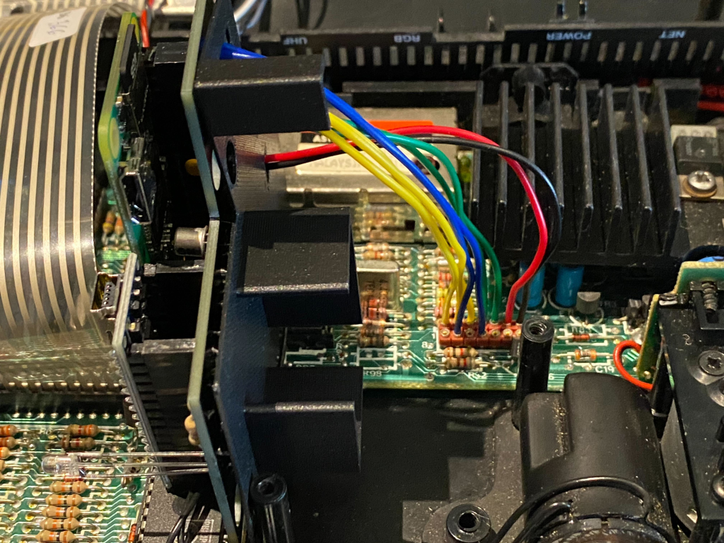
Internal PCB all wired up and working great. Basically the same as my standalone PCB but without the edge connectors and re-arranged to fit where mdv1 was.
TomD
TomD
-
Derek_Stewart
- Font of All Knowledge
- Posts: 4866
- Joined: Mon Dec 20, 2010 11:40 am
- Location: Sunny Runcorn, Cheshire, UK
Re: OqtaDrive
Hi Tom,
Do you have details of the supports under the PCBs?
Pity the Microdrive Pillars could not being used to mount the OqtaDrive PCB.
Do you have details of the supports under the PCBs?
Pity the Microdrive Pillars could not being used to mount the OqtaDrive PCB.
Regards, Derek
Re: OqtaDrive
Yes will put the STL on Thingiverse once I've finished.Derek_Stewart wrote:Hi Tom,
Do you have details of the supports under the PCBs?
Pity the Microdrive Pillars could not being used to mount the OqtaDrive PCB.
It is a pity it couldn't be screwed directly on but unfortunately it pushes everything too high in the case so the lid won't shut so a bit of a compromise. I did toy with mounting it upside down but it doesn't fit.
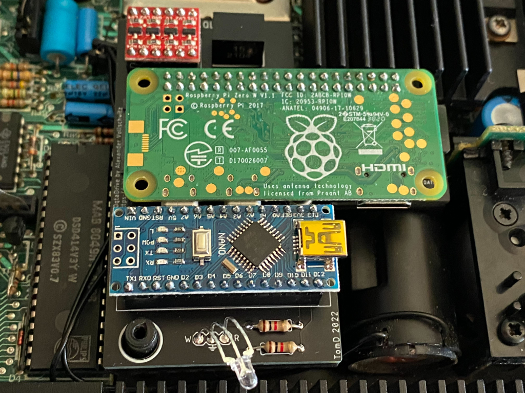
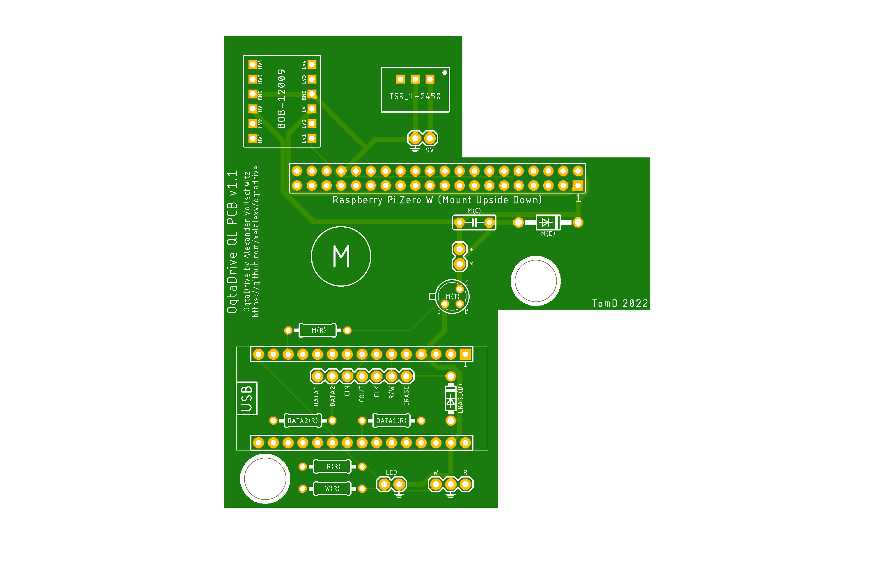
I've made some adjustments to the PCB design as well after testing. I've moved the pins under the Nano which makes it easier to route, plus added the pin out for connecting the case LED directly which was a great suggestion.

Re: OqtaDrive
This could be shrunk to be the same size as the Pi Zero by going directly to SMD components. With component shortages, the majority of Nanos have counterfeit ICs, and they're still extremely overpriced.
You could post the schematic, or I could look it up on github. Either way, I have plenty of the ATmega328 SMD parts in stock and it's a simple board, so it could be a quick turnaround. Then it would just be a matter of sending them to someone in the UK for distribution.
You could post the schematic, or I could look it up on github. Either way, I have plenty of the ATmega328 SMD parts in stock and it's a simple board, so it could be a quick turnaround. Then it would just be a matter of sending them to someone in the UK for distribution.
Re: OqtaDrive
Alex's github (https://github.com/xelalexv/oqtadrive) site has the circuit diagram, other than that I just connected the Pi's hardware serial (Tx/Rx GPIO 14 & 15) and a reset pin (GPIO 18) to the Nano via a bi-directional logic level convertor. I also used a TSR 1-2450 to get a stable 5V power for the board.Dave wrote:This could be shrunk to be the same size as the Pi Zero by going directly to SMD components. With component shortages, the majority of Nanos have counterfeit ICs, and they're still extremely overpriced.
You could post the schematic, or I could look it up on github. Either way, I have plenty of the ATmega328 SMD parts in stock and it's a simple board, so it could be a quick turnaround. Then it would just be a matter of sending them to someone in the UK for distribution.
The only issue with SMD is it makes it harder for people to adopt as not everybody comfortable soldering the tiny parts vs. through hole which is easier, so it would be selling complete boards minus the Pi. Anyway will be interesting to see how small you can get it including connectors.
Also worth mentioning that the counterfeit ICs do seem to work ok with this, I've tried a few cheapo ones and they've been fine.