Pr0f wrote: Thu Aug 03, 2023 3:28 pm
These capacitors labelled DCn (where n is some number) - are generally 100nF decoupling capacitors - any good quality 100n capacitor will do - but if you want to maintain the look and clearance of the original board - try and find the axial ones (wires sticking out either side of a cylinder). Voltage rating - 50v should be more than enough, but higher is no problem - size and clearance are the key things here.
Nice & thank you,
DCn I will use some that I have. What is about the others labeled as Cn? (where n is some number)
Those are also capacitors - but may have more specific purposes in the circuit. The service manual has a good list of components and types for the builds
Pr0f wrote: Thu Aug 03, 2023 4:09 pm
Those are also capacitors - but may have more specific purposes in the circuit. The service manual has a good list of components and types for the builds
That is what I checked out.
It says... 0.1uF, 50V, -20%+80%
But I'm newbie in this area, unable to tell if matters or not.
Placing the DCx capacitors...
1. DC28 & DC29 are placed in MDVs so nothing to deal with.
2. DC7 ... Where is it? I cannot find it anywhere on the board.
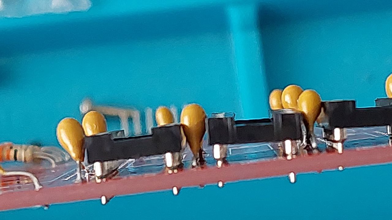
3. I wonder if with the type of capacitors that I am using could be problematic due to leads, how close are some leads to board tracks.
Sometimes they are just separated by the paint from tracks. Doesn't it generate capacitance somehow?
the only critical capacitors are those around the colour encoder chip near the UHF modulator - as these have to be certain values. Most of the other capacitors on the rest of the board are fine being lose on tolerance - but do follow the service manual for component values.
Some component numbering was retained from the issue 5 boards - so some components are no longer present - which seems to throw the numbering a little.
The proximity of component leads to the tracks on the board can largely be avoided by using the axial capacitors - not the radial ones you show in your picture.
Pr0f wrote: Fri Aug 04, 2023 12:03 am
the only critical capacitors are those around the colour encoder chip near the UHF modulator - as these have to be certain values. Most of the other capacitors on the rest of the board are fine being lose on tolerance - but do follow the service manual for component values.
Exactly what I am doing.
Pr0f wrote: Fri Aug 04, 2023 12:03 am
Some component numbering was retained from the issue 5 boards - so some components are no longer present - which seems to throw the numbering a little.
Oh I see. I took the numbers from service manual, but I see... so it is another mistake from the service manual.
Pr0f wrote: Fri Aug 04, 2023 12:03 am
The proximity of component leads to the tracks on the board can largely be avoided by using the axial capacitors - not the radial ones you show in your picture.
That was my previous question, yep. So it is better to buy a bunch of axial capacitors instead what I have placed. Isn't it?
Derek_Stewart wrote: Fri Aug 04, 2023 9:11 am
Looks to be a modification to Issue 6 boards, but not detailed in the scanned manual.
I will check this with my paper Service Manual.
Very interesting
I thought, the scanned manual should show the same than paper. But now you mention it and considering the bunch of mistakes in docs... it makes sense that even different manuals shows different information.
Thank you Derek
Edit: Also I see about xtals... and I wonder... what is the difference between low and "high" profile? (size). Mainly I can find low profile (not sure if that is right in English). But I hesitate about differences.
X4... Somebody knows where to buy this xtal of 11Mhz 10ppm?
Edit2:
Also I have notice other mistakes in the service manual (Scanned version)... C38,C40,C21,C22 are typed as Axial but they are actually Radial.