Page 1 of 2
JS ROM creation
Posted: Sun Oct 26, 2014 4:22 pm
by schombi
I need your help with this simple question. I have a British QL here, which I repaired, but the only two working ROM chips I have here are MGG. They do the job, but obviously not ideal to be used on this machine.
Is it possible to download e.g. the JS ROM files and burn them onto EPROM chips, like I did for my MicroP floppy controller? If so, what´s the required specification? The two QL ROM chips were always a mystery to me (why two and why are the sizes different?) and I really cannot interpret the writing on the chips. On the Spectrum it was not easy to replace the ROM chips with an home-made EPROM and some soldering had to be done in addition. Did Sinclair change its philosophy with the QL?
Re: JS ROM creation
Posted: Sun Oct 26, 2014 6:00 pm
by 1024MAK
What version PCB do you have?
A photo of the area of the board that shows the ROM socket area may help.
Why am I asking these questions? - Well, the most common boards are issue 5 and issue 6. The issue 5 can take ROMs or EPROMs. The issue 6 board is designed for ROM chips.
The issue 5 QL board was originally designed to have a number of configurations of ROM chip(s) or EPROM chip(s). Either one large one, or two smaller ones (but with both being the same size/type). There are link positions (for wire links, or zero ohm resistors) on the board.
However, SuperBASIC and QDOS did not fit in the allocated 32k byte space. So to get all the ROM/EPROMs inside, the board was modified to take one 32k byte ROM/EPROM and a 16k byte ROM/EPROM. Note that the wiring on the board is different depending on whether ROMs are fitted or EPROMs are fitted.
The Sinclair supplied ROMs have custom specified chip select inputs, which means the address decoding on the issue 6 board (or modified issue 5 boards) is simpler.
Mark
Re: JS ROM creation
Posted: Sun Oct 26, 2014 6:04 pm
by dex
Re: JS ROM creation
Posted: Sun Oct 26, 2014 6:43 pm
by schombi
Thanks for your inputs. So, it´s not that simple...

The main board is an Issue 5.
The wire links (I was not aware of such on a QL) are called JU1 to JU5? If so, my board has JU2, 3 and 4 fitted. Does this tell anything?
Re: JS ROM creation
Posted: Sun Oct 26, 2014 10:06 pm
by Dave
RWAP is selling JM ROMs for £8 and JS ROMS for £15. He's a very reputable seller, so you know they'll work. Look on sellmyretro.com:
http://www.sellmyretro.com/category/Ret ... Components
Re: JS ROM creation
Posted: Sun Oct 26, 2014 11:09 pm
by prime
In case anyone is interested, attached is the Eagle schematic for the little ROM adapter I made by etching a board, should be easy enough to knock up on a piece of stripboard or tri-pad...or even dead cockroach ala issue 1 spectrum.....
I used it to make my own Minerva upgrade but no reason why it can't have another version instead.
Cheers.
Phill.
Re: JS ROM creation
Posted: Mon Oct 27, 2014 7:36 am
by chriskgnr
Hi to all!
But if i want to put two eprom ic's, one 27(C)256 and one 27(C)128 with the JS version programmed, the JU jumpers how they must be configured?
Re: JS ROM creation
Posted: Mon Oct 27, 2014 10:00 am
by 1024MAK
You need more than just the correct PCB links, as
this photo shows:
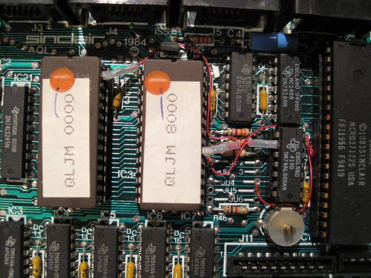 (click for the full image)
More later when I find my file with further details...
Mark
Re: JS ROM creation
Posted: Mon Oct 27, 2014 10:14 am
by 1024MAK
Attached is a spreadsheet that shows the pin-out of the ROM and of the sockets on a QL issue 5 board, along with ROM and EPROM pin-outs.
If you read this with a schematic and a copy of the service manual, you should be able to see how to configure a QL to take ROM chips or EPROM chips.
Mark
Re: JS ROM creation
Posted: Mon Oct 27, 2014 1:03 pm
by schombi
Thanks! That´s interesting stuff to know.
Just wonder why Sinclair made it that complicated, having e.g. a ROM upgrade of a SAM Coupe in mind?